Dupa plasarea solicitării de comandă, in sectiunea Istoric puteti vedea cate solicitări de comandă mai avem de procesat inaintea dumneavoastra
Program de lucru: Luni - Vineri 9:00 - 18:00, pauza 13:00 - 14:00.
Se efectueaza lucrari de mentenanta la site si pot aparea erori. In cazul in care intampinati erori va rugam sa reincercati mai tarziu.
Ridicarea personala este disponibila pentru comenzile achitate in avans. Se pot ridica dupa ce sunt pregatite.
No products
 View larger
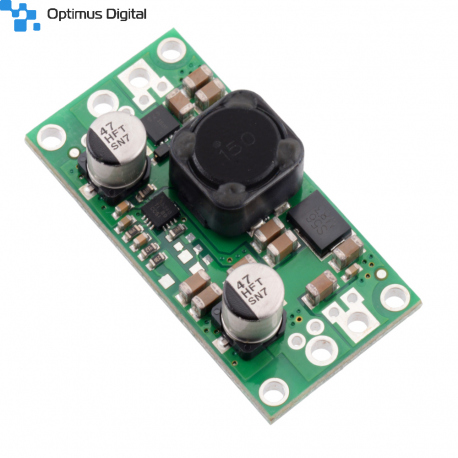
Pololu 24V Step-Up/Step-Down Voltage Regulator S18V20F24
0104110000068620
New product
This powerful step-up/step-down regulator efficiently produces a fixed 24 V output from input voltages between 3 V and 30 V while allowing a typical output current of up to 2 A when the input voltage is close to the output voltage and offering typical efficiencies of 80% to 90%. Its ability to convert both higher and lower input voltages makes it useful for applications where the power supply voltage can vary greatly, as with batteries that start above but discharge below the regulated voltage.
See description for more details about the product.
Add to cart now!
1 Item
Warning: Last items in stock!
- Write a review
- Remove this product from my favorite's list.
- Add this product to my list of favorites.
More info
Overview
These step-up/step-down regulators take an input voltage from 3 V to 30 V and increase or decrease it as necessary to produce a fixed 5 V, 6 V, 9 V, 12 V, or 24 V output, depending on the version. They are switching regulators (also called switched-mode power supplies (SMPS) or DC-to-DC converters) with a single-ended primary-inductor converter (SEPIC) topology, and they have a typical efficiency between 80% and 90%. The available output current is a function of the input voltage, output voltage, and efficiency (see the Typical Efficiency and Output Current section below), but it will be around 2 A when the input voltage is close to the output voltage.
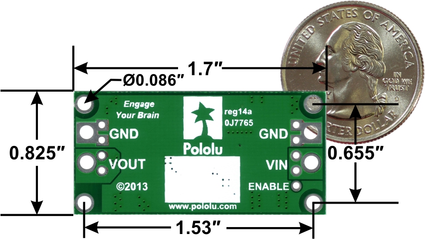
The S18V20x regulator family consists of the five fixed-output versions mentioned above along with two adjustable-output versions: the S18V20ALV offers an output range of 4 V to 12 V and the S18V20AHV offers an output range of 9 V to 30 V. The different versions of the board all look very similar, so the bottom silkscreen includes a blank space where you can add your own distinguishing marks or labels. This product page applies to all four fixed-output versions of the S18V20x family.
The flexibility in input voltage offered by these regulators is especially well-suited for battery-powered applications in which the battery voltage begins above the desired output voltage and drops below the target as the battery discharges. Without the typical restriction on the battery voltage staying above the required voltage throughout its life, new battery packs and form factors can be considered. For example:
• A 4-cell battery holder, which might have a 6 V output with fresh alkalines or a 4.0 V output with partially discharged NiMH cells, can be used with the 5V version of this regulator to power a 5 V circuit.
• A disposable 9 V battery powering a 5V circuit can be discharged to under 3 V instead of cutting out at 6 V, as with typical linear or step-down regulators.
• The 6V version of this regulator can be used to enable a wide range of power supply options for a hobby servo project.
The no-load quiescent current will typically be around 1 mA for most combinations of input and output voltages, though the combination of a very high output voltage and a very low input voltage (e.g. when boosting from 3 V in to 30 V out) can result in quiescent currents on the order of a few dozen milliamps.
The ENABLE pin can be used to put the board in a low-power state that reduces the quiescent current to between 10 and 20 µA per volt on VIN (e.g. approximately 30 µA with 3 V in and 500 µA with 30 V in).
This regulator has built-in reverse-voltage protection, over-current protection, thermal shutdown (which typically activates at 165°C), and an under-voltage lockout that causes the regulator to turn off when the input voltage is below 2.5 V (typical).
Features
• Input voltage: 2.9 V to 32 V1
• Fixed 5 V, 6 V, 9 V, 12 V, or 24 V output with 4% accuracy
• Typical maximum output current: 2 A (when input voltage is close to the output voltage; the Typical Efficiency and Output Current section below shows how the achievable output current depends on input and output voltages)
• Integrated reverse-voltage protection (up to 30 V), over-current protection, over-temperature shutoff, and under-voltage lockout
• Typical efficiency of 80% to 90%, depending on input voltage, output voltage, and load
• Four 0.086" mounting holes for #2 or M2 screws
• Compact size: 1.7" x 0.825" x 0.38" (43 x 21 x 10 mm)
• Smaller holes for 0.1" header pins and larger holes for terminal blocks offer several options for connecting to the board
1 32 V is the absolute maximum operating voltage; the recommended maximum operating voltage is 30 V, which is the limit of the reverse voltage protection.
Using the regulator
Connections
This step-up/step-down regulator has four connections: input voltage (VIN), ground (GND), and output voltage (VOUT), and ENABLE.

The input voltage, VIN, should be between 2.9 V and 32 V. Lower input voltages can cause the regulator to shut down or behave erratically; higher input voltages can destroy the regulator, so you should ensure that noise on the input is not excessive. 32 V should be treated as the absolute maximum input voltage. Our recommended maximum operating voltage is 30 V, which is the limit of the reverse voltage protection.
The regulator is enabled by default: a 100 kΩ pull-up resistor on the board connects the ENABLE pin to reverse-protected VIN. The ENABLE pin can be driven low (under 0.7 V) to put the board into a low-power state. The quiescent current draw in this sleep mode is dominated by the current in the pull-up resistor from ENABLE to VIN and by the reverse-voltage protection circuit, which will draw between 10 µA and 20 µA per volt on VIN when ENABLE is held low (e.g. approximately 30 µA with 3 V in and 500 µA with 30 V in). If you do not need this feature, you should leave the ENABLE pin disconnected. Note that the SEPIC topology has an inherent capacitor from input to output; therefore, the output is not completely disconnected from the input even when the regulator is shut down.
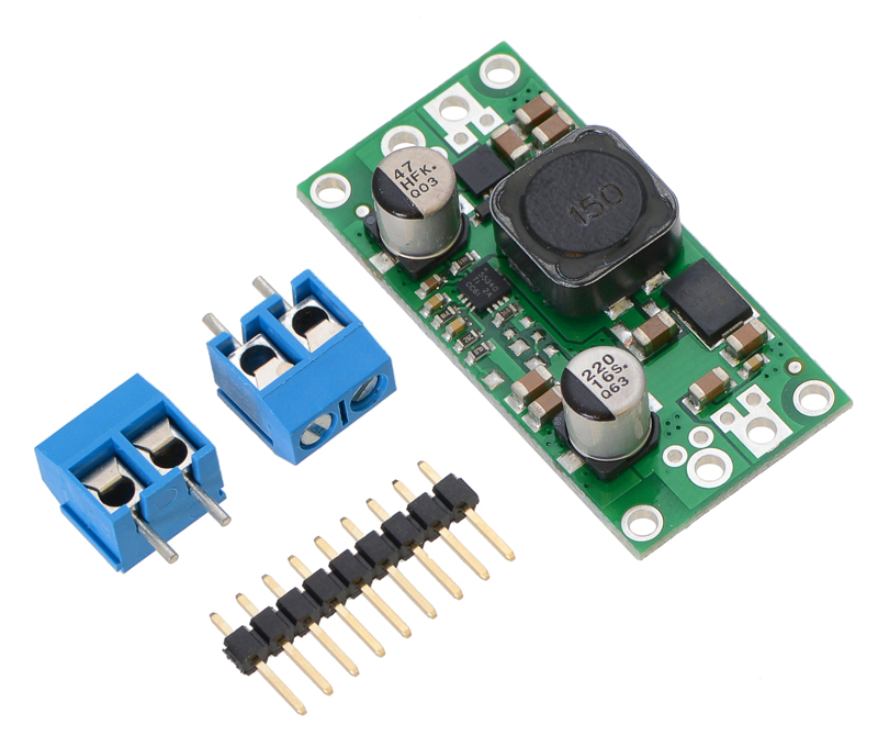
Pololu fixed step-up/step-down voltage regulator S18V20Fx with included optional terminal blocks and header pins.
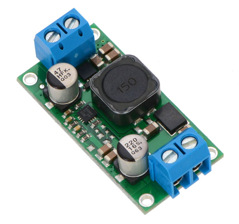
Pololu fixed step-up/step-down voltage regulator S18V20Fx, assembled with included terminal blocks.
The connections are labeled on the back side of the PCB, and the board offers several options for making electrical connections. You can solder the 2-pin 5mm-pitch terminal blocks to the two pairs of larger holes on the ends of the board. Alternatively, if you want to use this regulator with a solderless breadboard, 0.1"-pitch connectors, or other prototyping arrangements that use a 0.1"grid, you can solder pieces of the 9x1 straight male header strip to the 0.1"-spaced smaller holes (each large through-hole has a corresponding pair of these smaller holes). For the most compact installation, you can solder wires directly to the board.
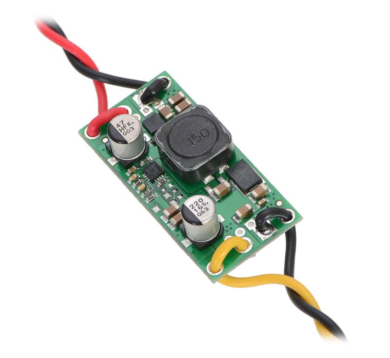
The board has four 0.086" mounting holes intended for #2 or M2 screws. In applications where mounting screws are not used and wires are soldered directly to the board, the insulated part of the wires can be passed through the mounting holes for strain relief. The picture above shows an example of this with 20 AWG wire, which was close to the limit of what would fit through the mounting holes.
Typical efficiency and output current
The efficiency of a voltage regulator, defined as (Power out)/(Power in), is an important measure of its performance, especially when battery life or heat are concerns. As shown in the graphs below, these switching regulators have an efficiency of 80% to 90% for most combinations of input voltage, output voltage, and load.
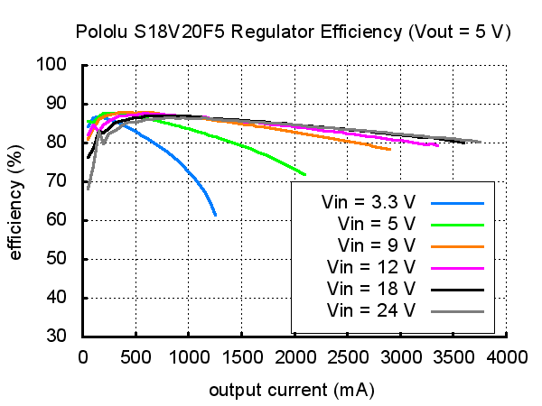
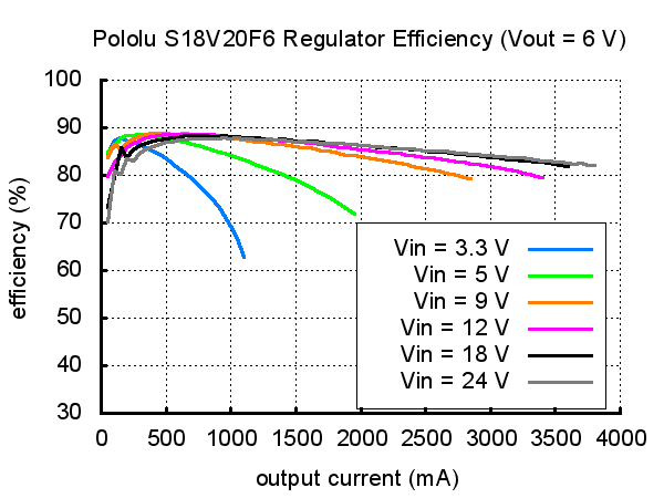
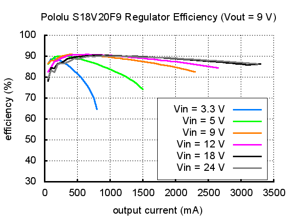
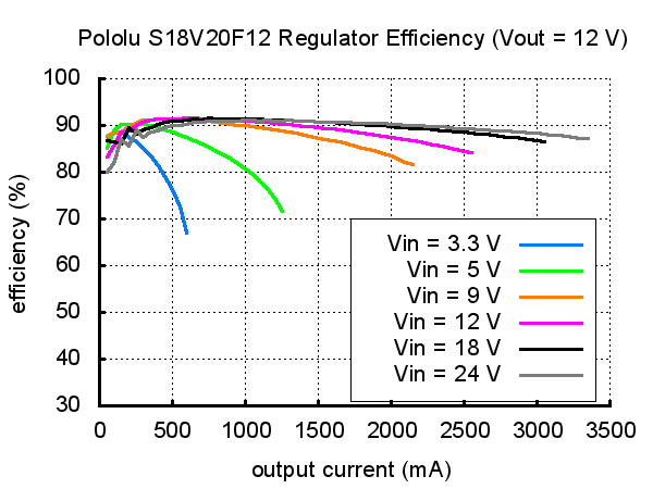
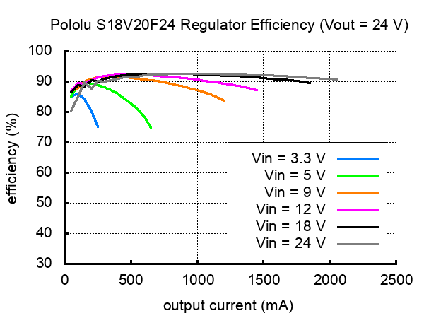
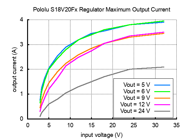
The maximum achievable output current of the board varies with the input voltage but also depends on other factors, including the ambient temperature, air flow, and heat sinking. The graphs below show output currents at which this voltage regulator’s over-temperature protection typically kicks in after a few seconds. These currents represent the limit of the regulator’s capability and cannot be sustained for long periods, so the continuous currents that the regulator can provide are typically several hundred milliamps lower.
During normal operation, this product can get hot enough to burn you. Take care when handling this product or other components connected to it.
Specifications
Dimensions
| Size: | 0.825" x 1.7" x 0.38"1 |
| Weight: | 7.5 g2 |
General specifications
| Minimum operating voltage: | 2.9 V |
| Maximum operating voltage: | 32 V3 |
| Maximum output current: | 2 A4 |
| Output voltage: | 24 V |
| Reverse voltage protection?: | Y |
| Maximum quiescent current: | 12 mA6 |
Notes:
1 Without included optional headers or terminal blocks. Height with terminal blocks installed is approximately 0.5".
2 Without included optional headers or terminal blocks. Terminal blocks add 3.4 g.
3 Absolute maximum. Recommended maximum operating voltage is 30 V, and reverse voltage protection only works up to 30 V.
4 Under typical conditions, where the input voltage is close to the output voltage. Maximum output current can be higher when stepping down and lower when stepping up.
5 For input voltages up to 30 V.
6 Typical worst case (i.e. with VIN at 3 V). Quiescent current depends on the input and output voltages and is much lower for most of the input voltage range. The ENABLE pin can be used to reduce the quiescent current to well under 1 mA.
Don't delay, buy today.
Add to cart now!
Reviews
Customers who bought this product also bought:
-
Raspberry Pi...
The Raspberry Pi AI Kit bundles an M.2-format...
$92.74
-

USB to...
This module converts the signal from a USB...
$1.49
-
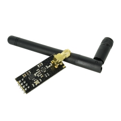
Long Range...
This is a 2.4 GHz nRF24L01 transceiver with PA...
$4.32
-
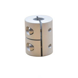
Coupling Hub...
Light weight, extremely low inertia and high...
$2.88
-

NRF24L01 2.4...
This module uses the nRF24L01 integrated...
$2.02


