Dupa plasarea solicitării de comandă, in sectiunea Istoric puteti vedea cate solicitări de comandă mai avem de procesat inaintea dumneavoastra
Program de lucru: Luni - Vineri 9:00 - 18:00, pauza 13:00 - 14:00.
Se efectueaza lucrari de mentenanta la site si pot aparea erori. In cazul in care intampinati erori va rugam sa reincercati mai tarziu.
Ridicarea personala este disponibila pentru comenzile achitate in avans. Se pot ridica dupa ce sunt pregatite.
Niciun produs
 Mărește
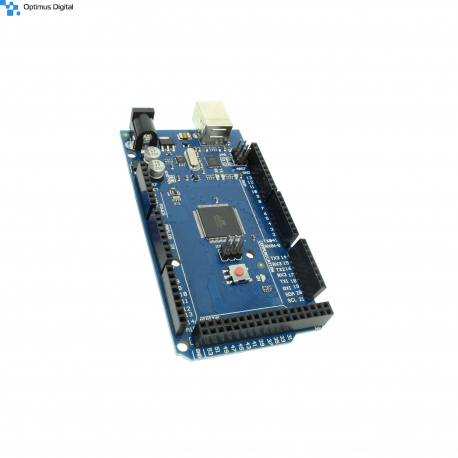
MEGA 2560 R3 (ATmega2560 + ATmega16u2) - Placa de Dezvoltare Compatibila cu Arduino
0104110000017017
Produs nou
Placa ideala pentru proiecte creative in domeniul electronicii. Ea utilizeaza microcontroller-ul ATmega2560 si microcontrollerul ATmega16u2 pentru conectivitate USB.
Cantitatea maximă care poate fi comandata: 3 buc
335 bucati in stoc
- Scrie o recenzie
- Elimina acest produs din lista mea de favorite.
- Adauga acest produs la lista mea de favorite.
- Imprimă
Accesorii
Accesorii Esențiale
Informații
Caracteristici tehnice:
- Tensiune de functionare: 5V;
- Tensiune de alimentare Jack: 7V - 12V;
- Pini I/O: 54;
- Pini PWM: 15 (din cei de I/O);
- Pini analogici: 16;
- 4 x UART;
- Memorie flash: 256KB, din care 8KB ocupati de bootloader;
- Frecventa de functionare: 16MHz.
Dimensiuni: 5.3cm x 10cm.
Aceasta placa de dezvoltare este perfecta pentru proiecte mai mari, ce au nevoie de multi pini de comunicatie, analogici si de pwm. De asemenea, microcontroller-ul ofera comunicatie SPI, UART si TWI.
Pentru a putea programa placa si pentru alte exemple: Download Arduino IDE.
Instrucțiuni de utilizare:
1. Instalați mediul de dezvoltare Arduino IDE.
Arduino IDE este disponibil gratuit pe site-ul oficial și poate fi descărcat accesând acest link. Acest program este compatibil cu majoritatea sistemelor de dezvoltare ( Linux, Mac OS X și Windows ).
2. Configurați mediul de dezvoltare pentru a fi folosit împreuna cu placa de dezvoltare.
Deschideți tab-ul "INSTRUMENTE" și selectați placă de dezvoltare "Arduino/Genuino Mega or Mega 2560". Acum selectați tipul de procesor "ATmega2560 (Mega 2560)".
3. Crearea codului.
După ce ați instalat Arduino IDE, puteți să scrieți primul program pentru placa de dezvoltare. Limbajul de programare utilizat este C++ ( ușor modificat ).
Codul are la bază doua funcții principale:
- Funcția "void setup()": Aceasta rulează o singură dată atunci când placa de dezvoltare este pornită. De obicei, această funcție este utilizată pentru inițializarea pinilor ( ca INPUT sau OUTPUT) sau pentru pornirea comunicării serial ( "Serial.begin" );
- Funcția "void loop()": Aceasta rulează la nesfârșit până când placa este oprită. De obicei, această funcție este utilă pentru a citi datele măsurate de diverși senzori atașați la placa de dezvoltare sau pentru a actualiza date pe un ecran LCD.
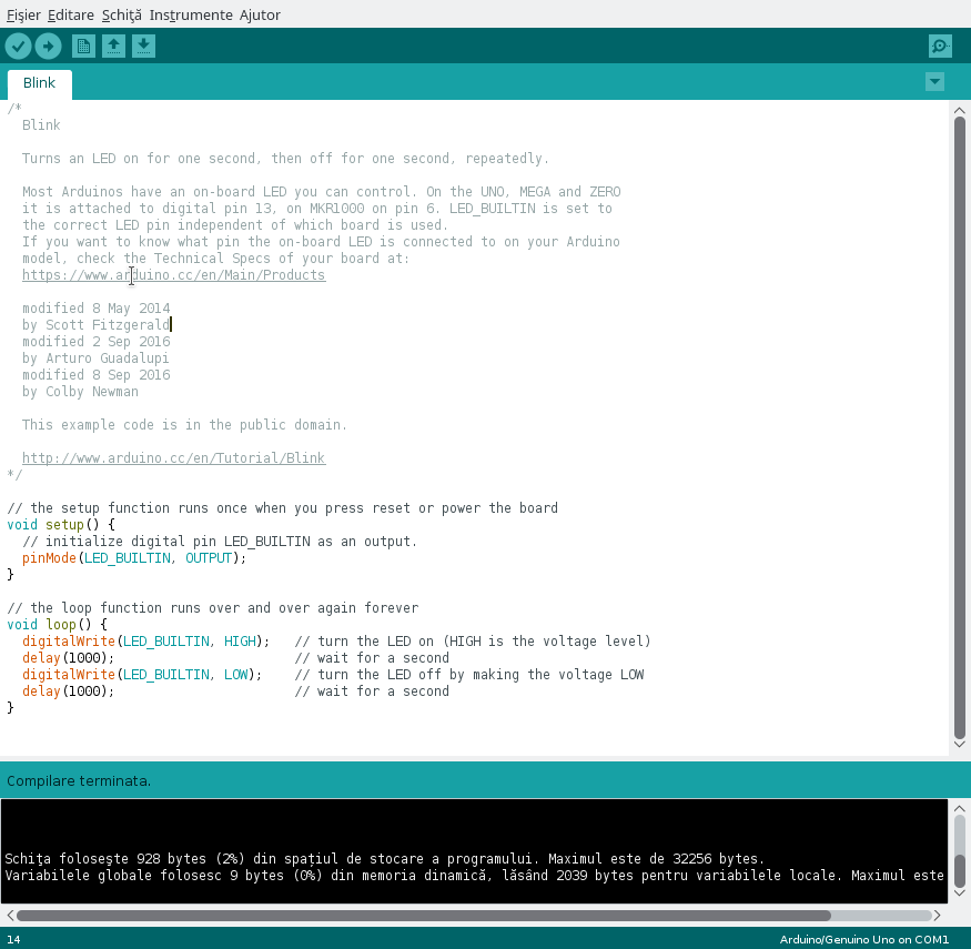
După ce ați scris programul sau ați deschis unul din Fișier -> Exemple, apăsați butonul "Verificare" sau scurtătura CTRL + R, pentru a compila codul. Dacă codul este lipsit de erori de sintaxă, în partea de jos ar trebuie sa apară textul "Compilare terminată". În caz contrat o să apară un mesaj de eroare care ar trebui să ajute la corectarea erorii.
În imaginea atașată mai jos puteți observa un exemplu de cod "Blink" care a fost compilat cu succes.
4. Conectați placa de dezvoltare și încărcați codul.
Conectați placa la calculator prin intermediul unui cablu USB. După ce ați conectat placa, deschideți tab-ul "INSTRUMENTE" și selectați portul la care este conectat dispozitivul.
Apăsați pe butonul "Încarcă" sau scurtătura CTRL + U pentru a încărca codul pe placa de dezvoltare. După finalizarea scrierii codului în memoria plăcii, o să primiți un mesaj de confirmare că nu au apărut probleme. În caz contrar, încărcarea este oprită și vor fi afișate detalii referitoare la problemele apărute.
5. Atașați senzorii.
Placa este compatibilă cu Arduino Mega 2560, așa că orice senzor pentru Arduino Mega 2560 poate fi folosit cu acest produs.
CAREFUL!!! Be careful not to connect components that consume too much power because you risk breaking the board. Also, observe the polarity of the sensors so as not to destroy them.
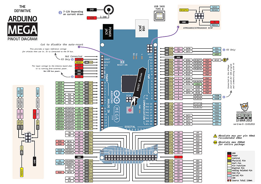
In the image attached below you can see the map of the pines. This is useful when you need to use special pins, such as PWM, ADC, SDA, SCL, etc.
Proiecte:
Recenzii
Clienții care au cumpărat acest produs au mai cumpărat:
-
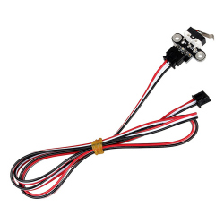
Întrerupător...
Întrerupător Limitator Orizontal Mecanic, în...
$1.68
-
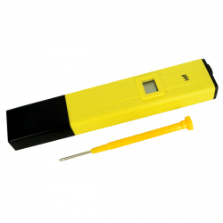
Tester PH...
Tester pH metru digital util pentru măsurarea...
$20.41
-
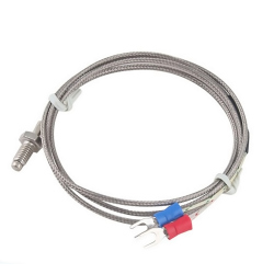
Termocuplu...
Termocuplu Tip K M6 (1 m)
$3.60
-
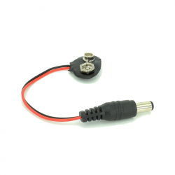
Fir pentru...
Fir pentru Baterie de 9V
$0.36
-
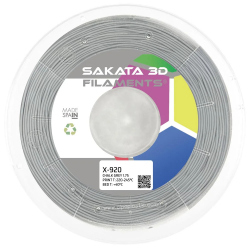
Filament...
Filamentul X-920 este fabricat dintr-un...
$16.80
-
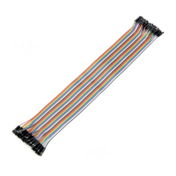
Fire...
Ideal wires for making connections between...
$1.92
-
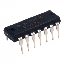
CD4011 (4...
CD4011 (4 porți logice de tip NAND)
$0.60
-
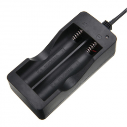
Incărcător...
Incărcător 18650 EU, pentru Baterii cu Litiu
$3.36
-
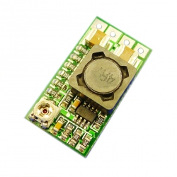
Sursă DC-DC...
Sursă DC-DC coborâtoare de 3 A cu eficiență...
$1.92
-
Piuliță...
Piuliță Autoblocantă M3
$0.12


