Dupa plasarea solicitării de comandă, in sectiunea Istoric puteti vedea cate solicitări de comandă mai avem de procesat inaintea dumneavoastra
Program de lucru: Luni - Vineri 9:00 - 18:00, pauza 13:00 - 14:00.
Se efectueaza lucrari de mentenanta la site si pot aparea erori. In cazul in care intampinati erori va rugam sa reincercati mai tarziu.
Ridicarea personala este disponibila pentru comenzile achitate in avans. Se pot ridica dupa ce sunt pregatite.
No products
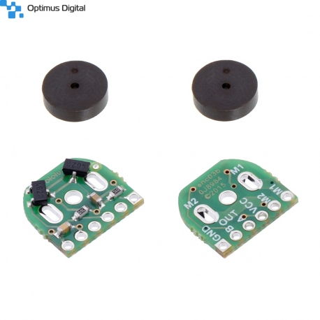 View larger
Magnetic Encoders for Micro engines (12 CPR, 2.7-18 V) - Compatible with HPCB Engines (2 pcs)
0104110000010292
New product
Add quadrature encoders to your micro metal gearmotors (extended back shaft version required) with this kit that uses a magnetic disc and Hall effect sensors to provide 12 counts per revolution of the motor shaft. The sensors operate from 2.7 V to 18 V and provide digital outputs that can be connected directly to a microcontroller or other digital circuit. These encoders have their pins arranged as through-holes on a 2mm pitch, and wires or 2mm-pitch connectors must be soldered in to use them. This module is compatible with all of the dual-shaft micro metal gearmotors we carry, including the HPCB versions.
See description for more details about the product.
Add to cart now!
This product is no longer in stock
- Write a review
- Remove this product from my favorite's list.
- Add this product to my list of favorites.
More info

Side-by-side comparison of Magnetic Encoder with Top-Entry Connector (left), Side-Entry Connector (center), and 2mm-pitch through-holes (right).
Overview
The encoder board senses the rotation of the magnetic disc and provides a resolution of 12 counts per revolution of the motor shaft when counting both edges of both channels. To compute the counts per revolution of the gearbox output shaft, multiply the gear ratio by 12.
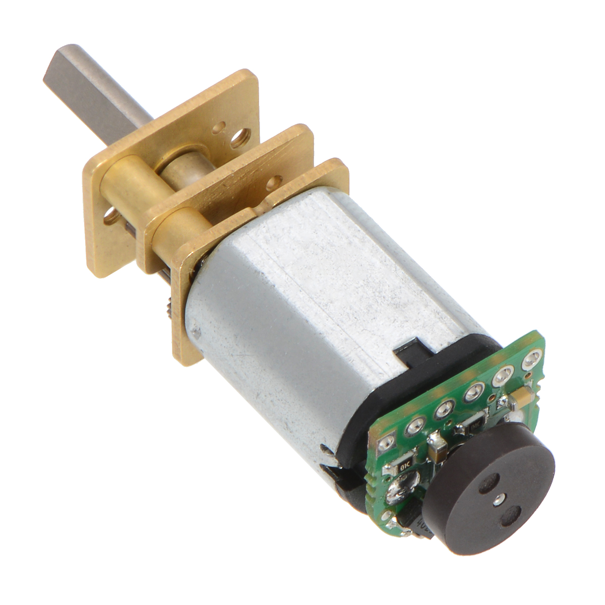
This compact encoder solution fits within the 12 mm x 10 mm cross section of the motors on three of the four sides, and it only extends 0.6 mm past the edge of the fourth side (note: if you need it to be flush with that last side, you can carefully grind the board down a little and solder to the remaining half-holes). The assembly does not extend past the end of the extended motor shaft, which protrudes 5 mm beyond the plastic end cap on the back of the motor.
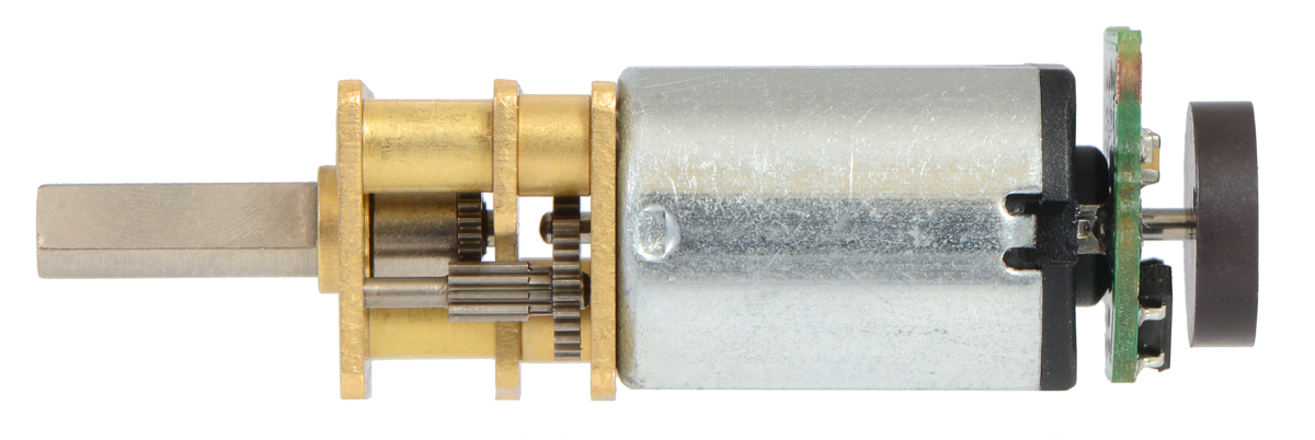
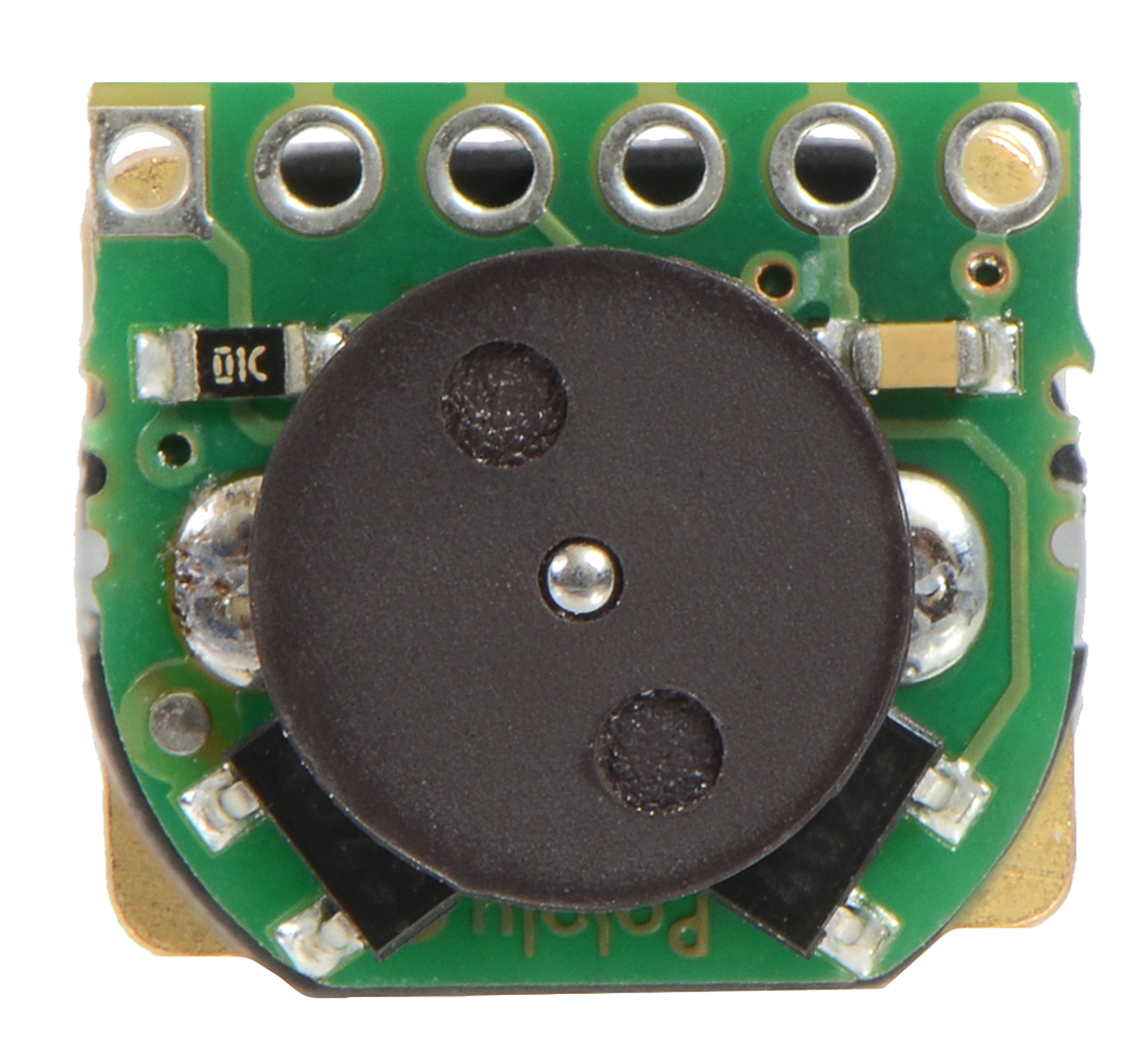
Note: This sensor system is intended for users comfortable with the physical encoder installation. It only works with micro metal gearmotors that have extended back shafts.
Pinout and installation
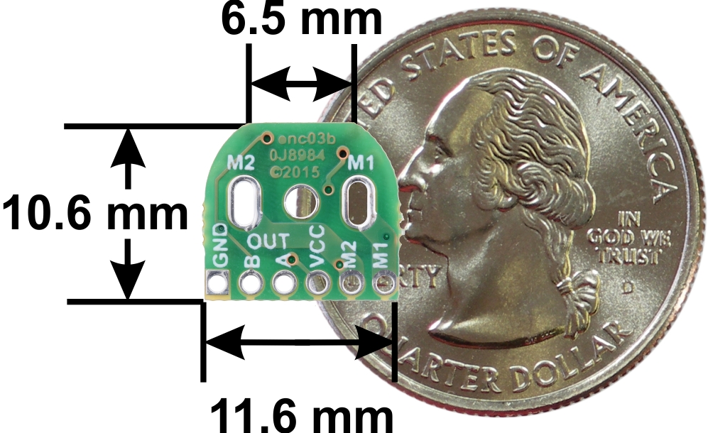
The encoder board is designed to be soldered directly to the back of the motor, with the back shaft of the motor protruding through the hole in the middle of the circuit board. One way to achieve good alignment between the board and the motor is to tack down the board to one motor pin and to solder the other pin only when the board is flat and well aligned. Be careful to avoid prolonged heating of the motor pins, which could deform the plastic end cap of the motor or the motor brushes. Once the board is soldered down to the two terminals, the motor leads are connected to the M1 and M2 pads along the edge of the board; the remaining four pads are used to power the sensors and access the two quadrature outputs:
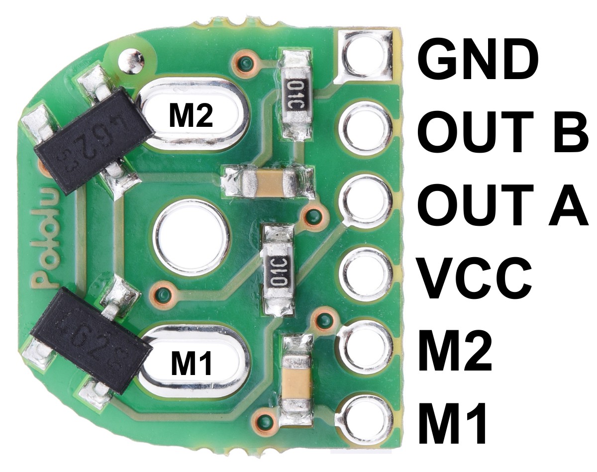
The sensors are powered through the VCC and GND pins. VCC can be 2.7 V to 18 V, and the quadrature outputs A and B are digital signals that are either driven low (0 V) by the sensors or pulled to VCC through 10 kΩ pull-up resistors, depending on the applied magnetic field. The sensors’ comparators have built-in hysteresis, which prevents spurious signals in cases where the motor stops near a transition point.
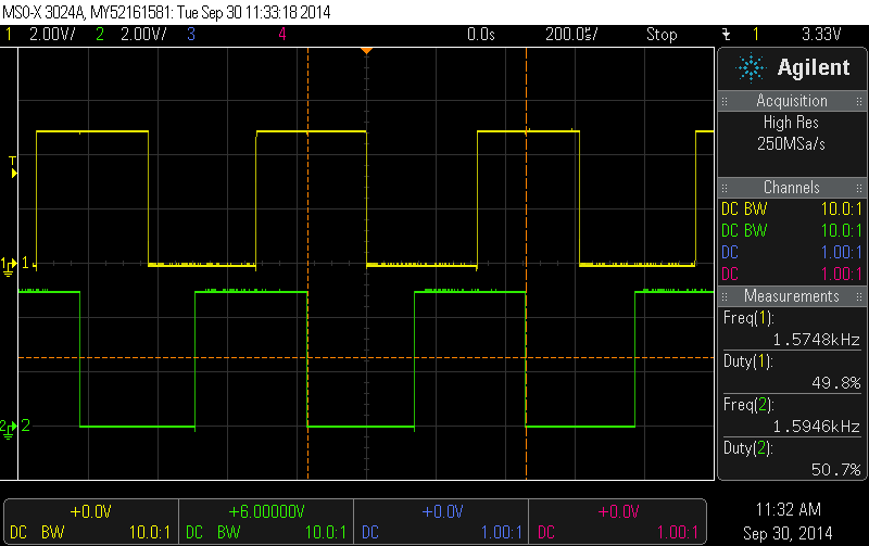
Encoder A and B outputs of a magnetic encoder on a high-power (HP) micro metal gearmotor running at 6 V
The board’s six pads have a 2 mm pitch, so they do not work with common 0.1" connectors. One option for connecting to the board is to solder in individual wires, such as in the example below:
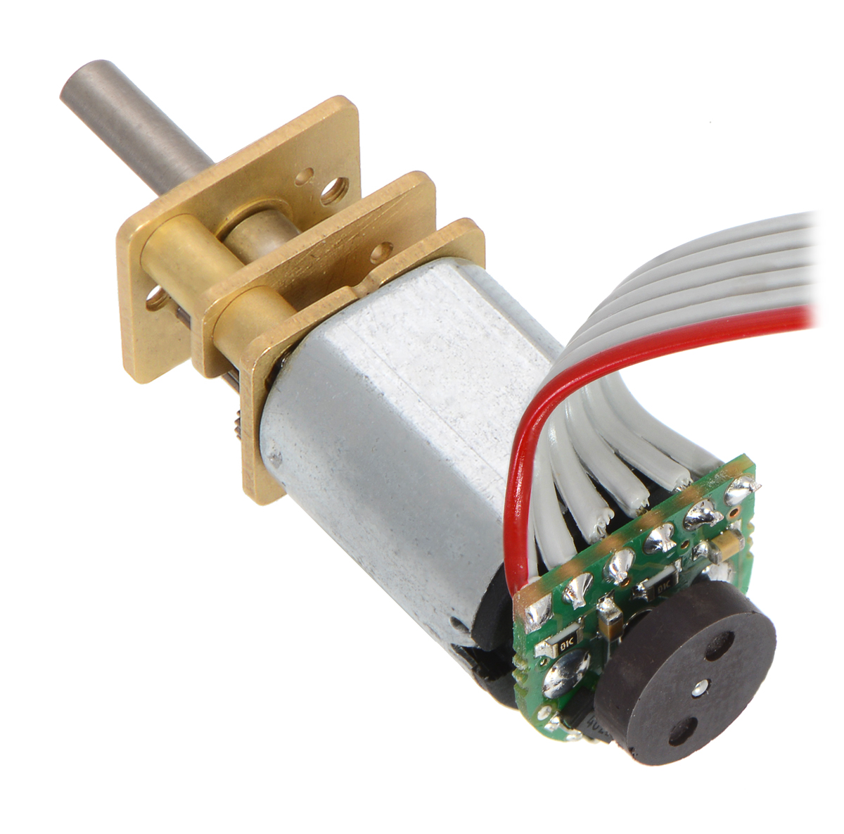
Alternatively, you can solder a 2mm-pitch connector to the board. The examples below show a male header, which gives you the option of making a detachable cable terminated by a 6-pin 2mm-pitch female header. If the pins are angled over the motor, as shown in the picture below, they will just barely protrude through the holes in the board. Note that in this orientation, there is room to plug in a female header even when an extended micro metal gearmotor bracket is being used.
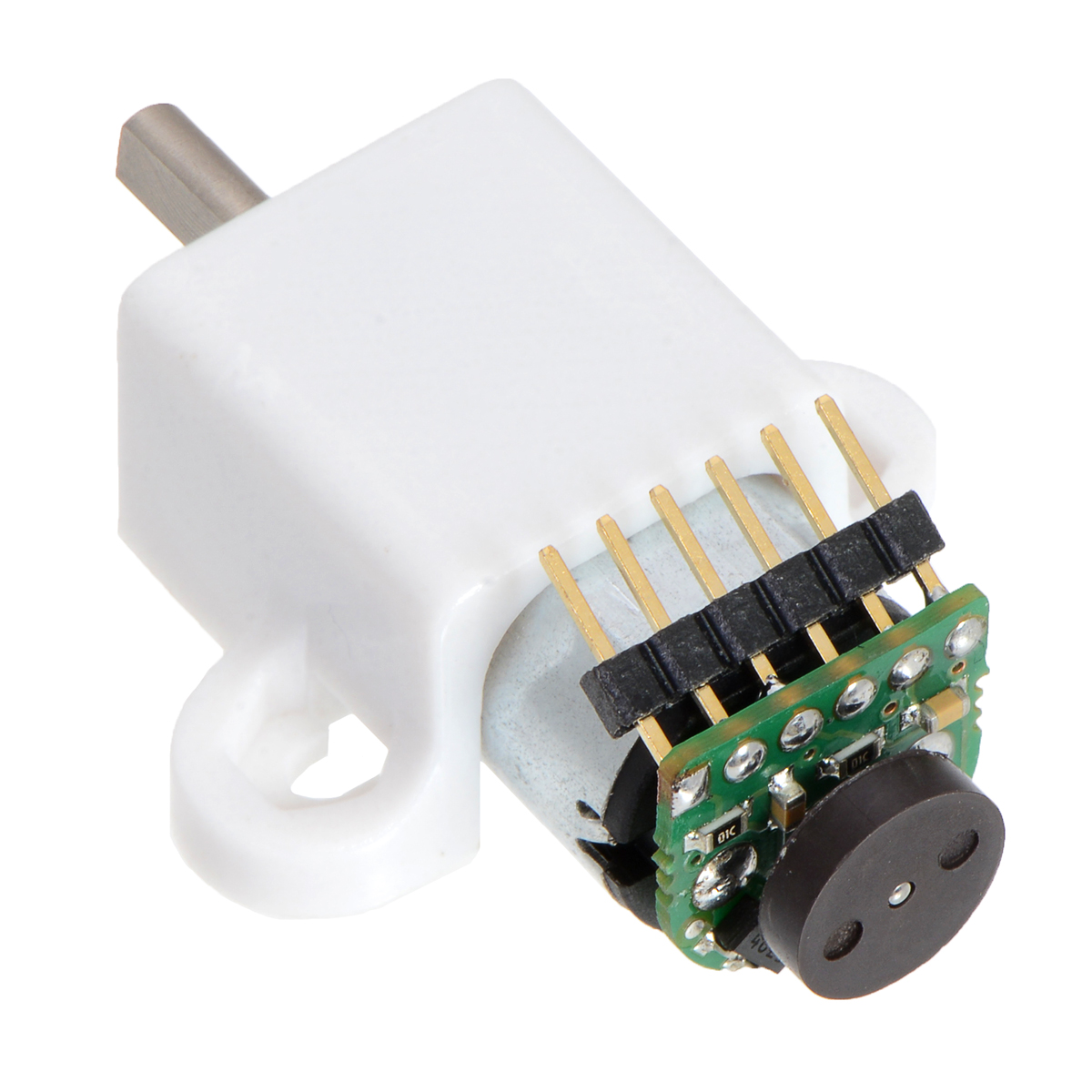
If the pins are pointed away from the motor, they will need to be angled so that they sufficiently clear the magnetic disc. With a decent soldering iron, it is possible to solder them in this orientation even after the encoder has been installed on the motor.
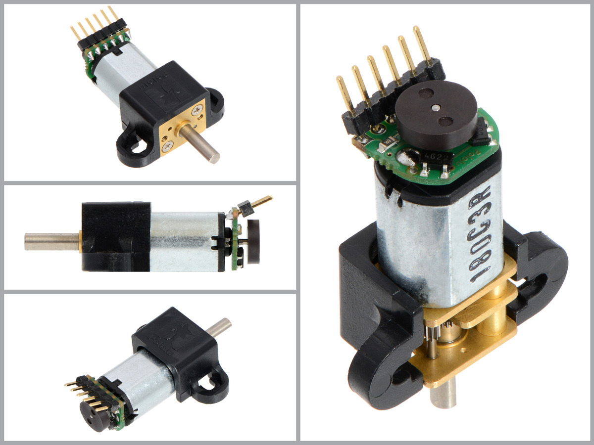
Once the board is soldered to the motor, the magnetic encoder disc can be pushed onto the motor shaft. One easy way to accomplish this is to press the motor onto the disc while it is sitting on a flat surface, pushing until the shaft makes contact with that surface. The size of the gap between the encoder disc and the sensor board does not have a big impact on performance as long as the motor shaft is at least all the way through the disc.
Schematic diagram
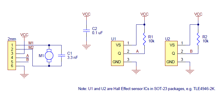
This schematic is also available as a downloadable pdf (125k pdf).
Specifications
Dimensions
| Size: | 10.6 mm x 11.6 mm1 |
| Weight: | 1.0 g2 |
General specifications
| Minimum operating voltage: | 2.7 V |
| Maximum operating voltage: | 18 V |
| Connector: | none (2mm-pitch through-holes) |
Notes:
1 The assembled encoder will extend 5 mm beyond the plastic motor end cap (it fits entirely within the length of the extended motor shaft).
2 Weight of full set. Each encoder board weighs ~0.2 g and each magnet disc weighs ~0.3 g.
Don't delay. Buy today.
Add to cart now!
Reviews
Customers who bought this product also bought:
-
SG90 180°
Micro 180o Servo Motors SG90 useful for...
11,99 lei
-
LM2596 DC-DC...
This an LM2596 DC-DC module with voltage...
16,49 lei
-
CGM12-N20VA-...
CGM12-N20VA-8200E Micro Gearmotor with Encoder...
52,00 lei
-
5p Female...
5p Female Pin Header 2.54 mm See description...
0,49 lei
-
DRV8833 Dual...
This tiny breakout board for TI’s DRV8833 dual...
74,99 lei
-
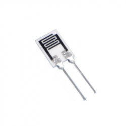
HR202L...
The HR202L is a new type of organic polymer...
3,99 lei
-
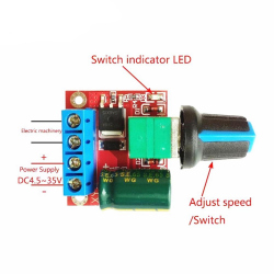
Mini PWM...
The mini PWM motor speed controller features...
24,99 lei
-
M2 White...
M2 White Plastic Screw with Round Head (5 mm)
0,10 lei
-

3xR6 Battery...
This is battery holder with 3 chambers for R6...
3,95 lei
-
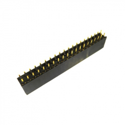
2x20p Female...
2x20p Female Pin Header 2.54 mm (for Raspberry...
1,92 lei


